Site guide
Vaulted Ceiling Insulation Planning: Spray-Foam Thickness, Roof Venting, R-Value, and Material Volume
Plan vaulted-ceiling spray foam by separating vent strategy, product-specific R-value and thickness, sloped ceiling geometry, board-foot volume, moisture control, and installer review.
BuildListCalc Editorial Team · 10 min · Published September 16, 2026 · Updated September 16, 2026 · Fact checked September 12, 2026
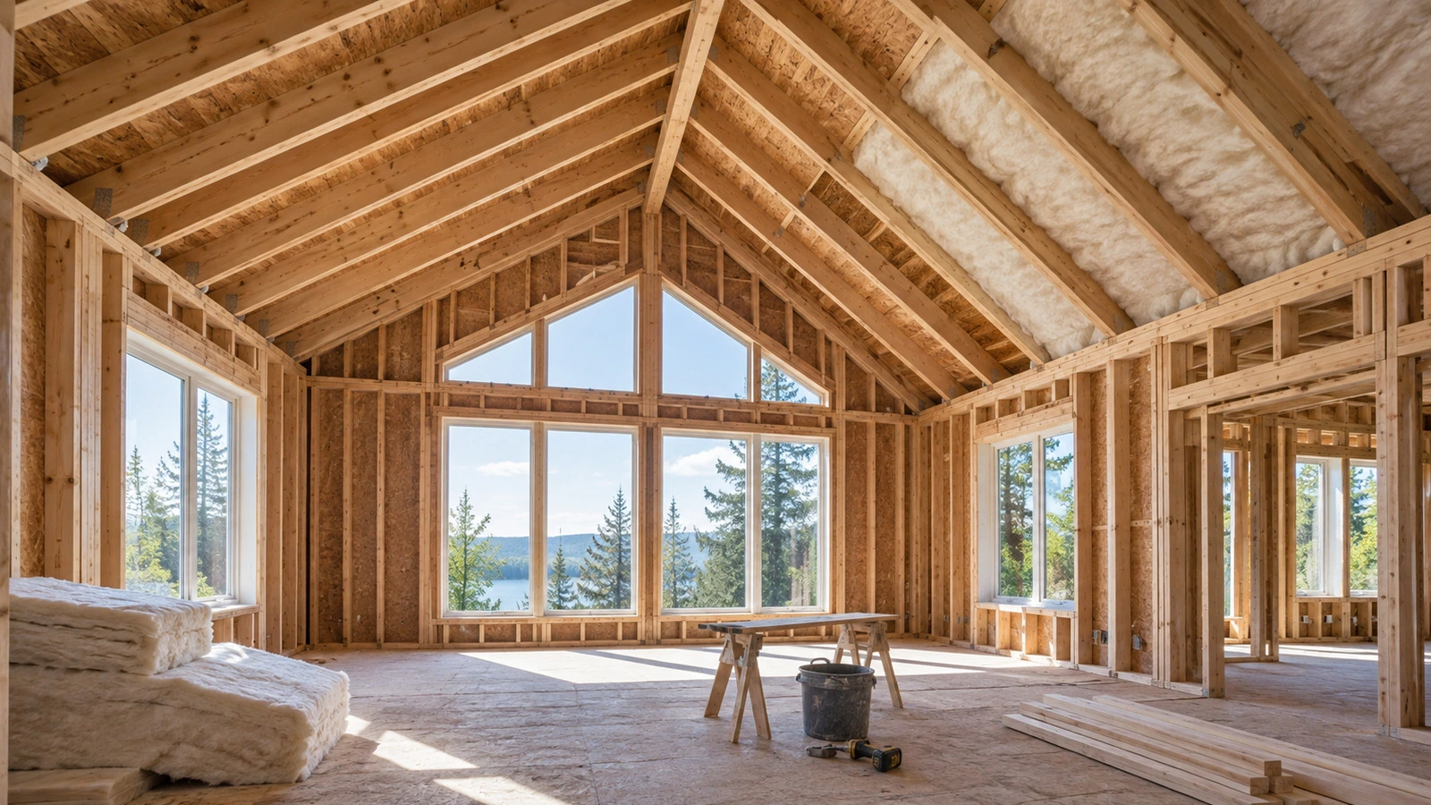
A vaulted ceiling compresses several decisions into one shallow roof assembly: insulation thickness, roof ventilation, moisture control, air sealing, fire protection, and usable cavity depth. That makes a simple “square feet × R-value” shortcut risky. Before you estimate spray foam, decide what roof assembly you are actually planning.
BuildListCalc’s current insulation tools support a vaulted / low-cavity ceiling path modeled with closed-cell spray foam and a planning basis of ceiling area × target thickness. The public BuildListCalc guidance also describes vaulted spray foam as a review-line allowance, not a permit-ready roof design. [S01]
This guide keeps four questions separate: Is the roof vented or unvented? What R-value does the accepted assembly require? What thickness does the selected foam product need? How much installed foam volume does that thickness represent?
1. Decide the roof path before you calculate foam
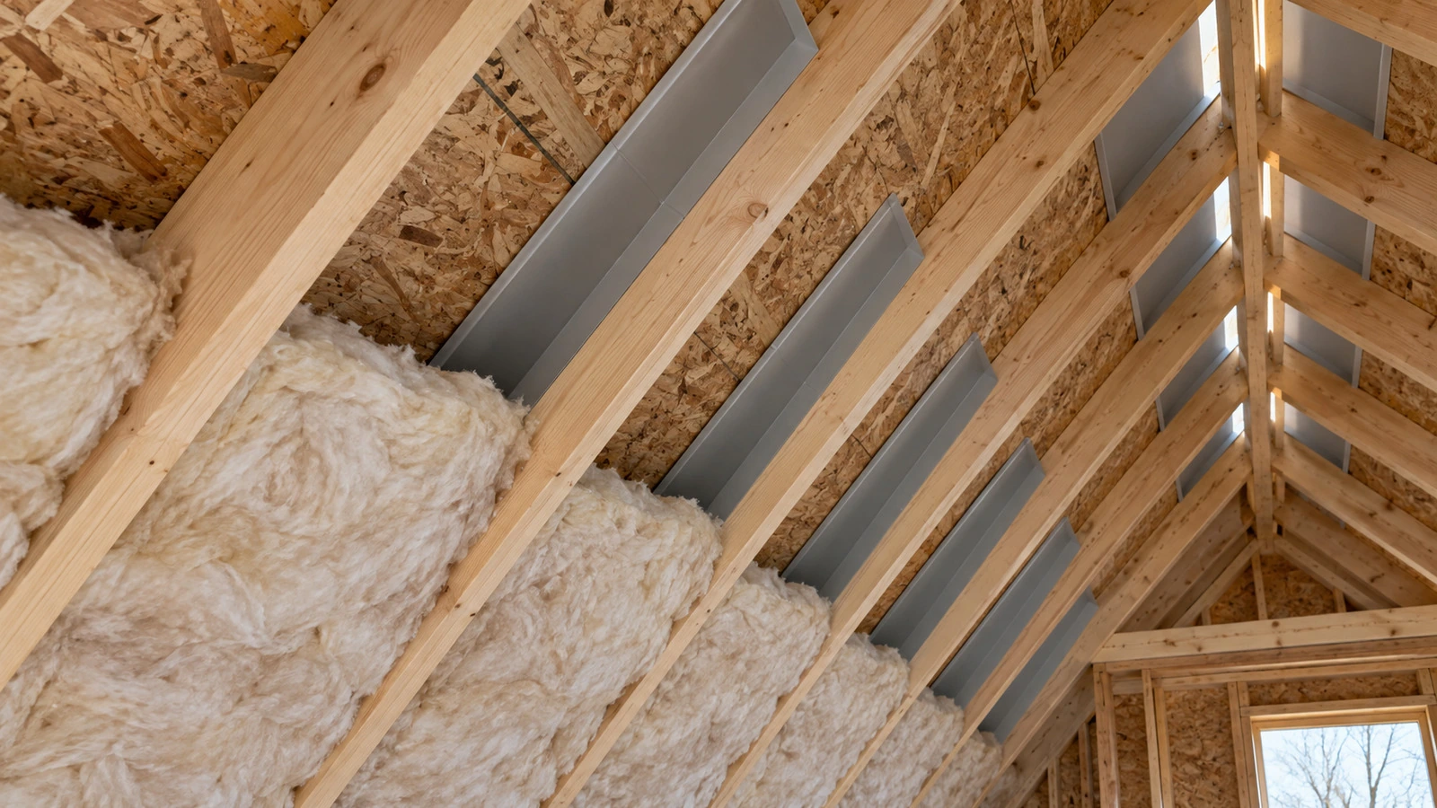
A vented cathedral ceiling and an unvented spray-foamed roof are not the same assembly with different insulation products.
In a vented cathedral ceiling, the roof needs a continuous ventilation route from the soffit toward the ridge above the insulation. A current Building America climate-zone example uses a baffle to preserve a 2-in. ventilation space beneath the roof sheathing and continuous soffit/ridge ventilation. That is an example assembly, not a universal dimension for every roof. [S03]
In an unvented roof, spray polyurethane foam can be installed at the underside of the roof deck as part of an air-impermeable roof assembly. Building America guidance describes both open-cell and closed-cell spray foam in unvented roof assemblies, but it also requires the roof to be intentionally designed without vents and calls for moisture removal through conditioning, dehumidification, or controlled ventilation. [S02]
Do not leave a vented roof half-open and then fill its ventilation path with foam. And do not block vents simply because the material estimate looks easier. The vent strategy is an assembly decision that belongs with the project documents, local code review, and the insulation/roofing professional.
2. BuildListCalc estimates volume; it does not choose the vent strategy
The current BuildListCalc insulation catalog says the calculator supports vaulted spray-foam ceilings. A related current BuildListCalc planning guide describes the modeled path as closed-cell spray foam, with the quantity basis ceiling area × target thickness, because cavity depth and vent strategy change quickly in vaulted conditions. [S01]
That is a useful estimating boundary. The calculator can help turn geometry and thickness into a material allowance, but it does not prove that:
- the roof should be vented or unvented;
- a particular foam formulation is accepted for the assembly;
- the selected thickness satisfies the locally adopted energy code;
- vapor control is complete;
- roof sheathing is dry enough to cover;
- an ignition or thermal barrier is unnecessary; or
- the roof framing is deep enough for the proposed assembly.
Treat the calculator output as a quantity basis after the roof concept is defined, not as the thing that defines the roof concept.
3. Measure the sloped ceiling area—not the room’s floor area
For a vaulted ceiling, use the actual sloped plane dimensions. If the ceiling has two roof planes, calculate each plane separately.
Consider a simple gable room with:
- room length: 20 ft;
- sloped ceiling length from eave line to ridge on each side: 12 ft;
- two equal ceiling planes.
One plane is:
20 ft × 12 ft = 240 sq ft
Both planes together are:
240 × 2 = 480 sq ft
That 480 sq ft is the geometry for the spray-foam volume example below. It is not a code-required area, a package coverage, or a purchase quantity.
If the ceiling contains skylights, dormers, beams, or areas that will use a different insulation system, measure those conditions explicitly instead of assuming the floor footprint represents the roof surface.
4. Thickness comes from the accepted assembly and the selected product
R-value and thickness are related, but there is no single universal “closed-cell foam = exactly R-X per inch” rule that should replace the current product data.
For example, DuPont’s current Froth-Pak product information lists an aged thermal resistance of about R-6.2 at 1 in. and R-12.2 at 2 in., and the current Froth-Pak 630 page describes approximately 630 board feet at 1-in. thickness. [S04]
Use those values as product-specific examples, not as a generic specification for every spray foam. Different products can have different tested R-values, maximum pass thicknesses, vapor permeance, ignition/thermal-barrier requirements, substrate limits, and application temperatures.
Building America examples also show why generic thickness rules are dangerous. One current resource illustrates 7 in. of closed-cell spray foam at R-49 in an unvented vaulted roof, while another cathedral-ceiling example uses a combination of closed-cell and open-cell foam. Those are documented example assemblies, not automatic targets for your project. [S02] [S05]
The practical sequence is:
- confirm the vented or unvented roof concept;
- confirm the required whole roof/ceiling performance with the AHJ or project documents;
- select an approved foam product/system;
- use that product’s current tested data to resolve thickness;
- only then convert thickness into material volume.
5. Material volume is area × thickness
Spray-foam estimating is often expressed in board feet. For planning math, one board foot corresponds to one square foot at one inch of thickness, so:
Board feet = ceiling area (sq ft) × foam thickness (in.)
Use the 480-sq-ft vaulted ceiling above and an example 5-in. target thickness. Five inches is only an example input here; it is not a code requirement or a manufacturer recommendation.
480 sq ft × 5 in. = 2,400 board ft
Because 12 board feet equal one cubic foot:
2,400 ÷ 12 = 200 cu ft of theoretical installed foam volume
If you wanted to show a visible example 10% planning allowance for overspray, trimming, substrate irregularity, and other field losses:
2,400 × 1.10 = 2,640 board ft
Again, 10% is an editorial example, not a universal waste factor and not a BuildListCalc default.
This distinction matters because a foam job can have three different numbers:
- theoretical installed volume;
- manufacturer theoretical kit/cylinder yield; and
- actual field consumption.
Those numbers should not be silently treated as identical.
6. A kit’s theoretical yield is not guaranteed field coverage
DuPont’s current product sheet lists theoretical yields for its portable systems and explicitly says the theoretical calculation is based on ideal laboratory conditions and does not account for losses from blowing agent or variations in application methods and types. [S04]
For example, dividing the 2,400-board-ft theoretical ceiling volume by a nominal 630-board-ft kit gives:
2,400 ÷ 630 = 3.81 theoretical kits
Mathematically, that rounds up to 4 theoretical kits before any field-loss allowance.
That is a unit-conversion example—not a recommendation to buy four portable kits for a full vaulted ceiling. Large roof applications are commonly contractor-scale spray work, and the selected product, spray equipment, lift/pass limits, substrate condition, installer method, temperature, and job geometry affect actual consumption.
Use board-foot math to communicate the scope to an installer or supplier. Use the selected system’s current yield data and installer plan to decide what actually gets ordered.
7. Roof venting can consume cavity depth
If the accepted design is a vented cathedral ceiling, part of the rafter depth belongs to the ventilation channel, not to insulation.
A current Building America Climate Zone 5 cathedral-ceiling example shows a 2-in. vent space beneath the roof sheathing maintained by an insulation baffle. In that specific 16-in. I-joist example, the vent channel leaves roughly 14 in. available for fibrous insulation. [S03]
The important planning lesson is not “every roof needs 2 inches.” It is that vent space occupies real depth. If you estimate insulation using the full rafter depth and later discover that a continuous ventilation channel must remain, the proposed insulation thickness may not fit.
Before ordering or spraying, record:
- rafter or I-joist depth;
- required ventilation-channel depth for the accepted assembly;
- thickness of any below-rafter or above-deck insulation;
- interior finish and service-space layers; and
- the actual remaining depth available to insulation.
8. An unvented spray-foam roof still has moisture rules
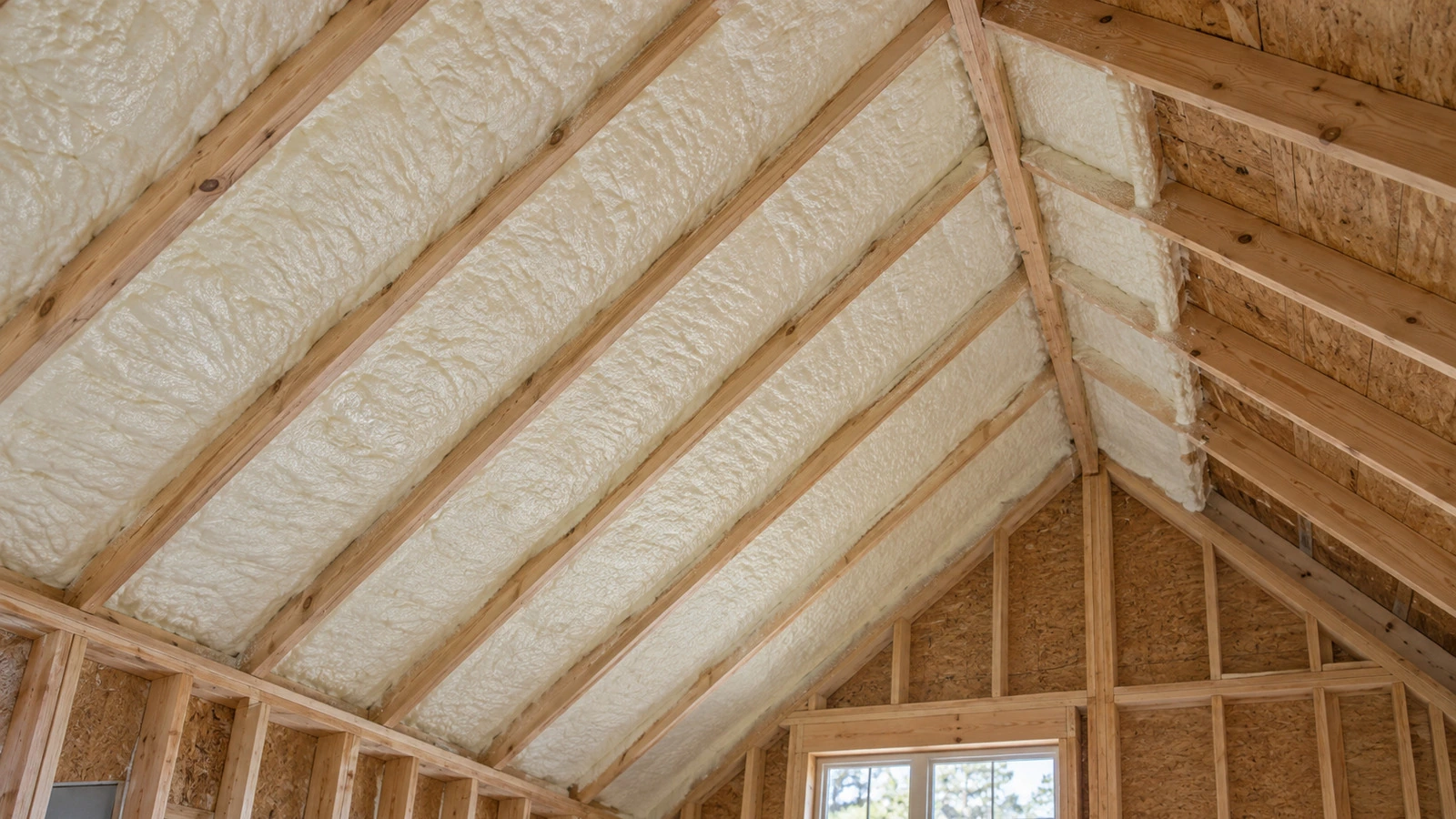
“No roof vents” does not mean “no moisture design.”
Building America guidance for spray foam below an existing roof deck says to correct roof leaks before insulating, verify roof condition, and ensure roof sheathing and framing are below 19% moisture content before spray foam is installed. It also describes vapor-control differences between open-cell and closed-cell foam and calls for conditioning, dehumidification, or controlled ventilation in the unvented space. [S02]
Closed-cell spray foam can provide both thermal and vapor control in some unvented roof assemblies, while open-cell foam remains more vapor open and may need an additional vapor-control layer depending on climate and assembly. [S02]
Those are design and product-selection questions, not a reason to increase the calculator thickness until the R-value looks large enough.
9. Do not ignore thermal and ignition barriers
Spray polyurethane foam is not automatically ready to remain exposed after installation.
Building America notes that a thermal or ignition barrier—such as gypsum board, a coating, or another approved material—may be necessary depending on the foam’s properties and code requirements. [S02]
The barrier decision affects:
- finished ceiling build-up;
- cavity depth and clearances;
- sequencing and inspections;
- material cost; and
- whether the foam remains accessible or exposed.
Keep that scope separate from the foam-volume math unless the calculator or contractor proposal explicitly includes it.
10. Spray foam application is also a jobsite-safety decision
Two-component spray polyurethane foam creates vapors, aerosols, and particulates that require controlled work practices. EPA guidance emphasizes ventilation, containment, personal protective equipment, keeping unprotected occupants and other trades away from the work area, and following product-specific re-entry instructions. [S06]
For a large vaulted ceiling, this is another reason to treat the material takeoff as a planning tool rather than an invitation to spray a large roof cavity without appropriate training, ventilation, respiratory protection, and product-specific procedures.
The article’s volume math can help you compare proposals or explain the scope. It does not replace an installer’s safety plan.
11. Keep five numbers separate in the takeoff
A useful vaulted-ceiling spray-foam takeoff records these values separately:
| Number | What it means |
|---|---|
| Sloped ceiling area | Actual roof/ceiling geometry being insulated |
| Target foam thickness | Example or approved installed thickness |
| Theoretical board feet | Area × thickness |
| Product theoretical yield | Manufacturer’s idealized yield basis |
| Purchase/installer quantity | Actual material allowance after system and field conditions are considered |
For the worked example:
- two ceiling planes: 480 sq ft total;
- example thickness: 5 in.;
- theoretical installed volume: 2,400 board ft;
- theoretical cubic volume: 200 cu ft;
- example 10% planning allowance: 2,640 board ft.
These are planning quantities. They do not certify the R-value, vent path, vapor control, code compliance, or actual field yield.
12. A practical planning sequence
Before you turn a vaulted ceiling into a spray-foam order:
- Measure the actual sloped ceiling planes, not just the floor footprint.
- Identify the roof strategy: vented cathedral ceiling, unvented roof, or another approved assembly.
- Inspect roof condition and moisture before covering the underside of the roof deck.
- Confirm the locally accepted R-value/compliance path and any required documentation.
- Select the actual spray-foam system and review its R-value, vapor properties, pass limits, substrate conditions, yield basis, and barrier requirements.
- Resolve the installed thickness from the approved assembly and product data.
- Calculate board feet from area × thickness.
- Keep theoretical yield separate from field consumption and get the installer/supplier’s material allowance.
- Coordinate ventilation, conditioning, vapor control, thermal/ignition barriers, electrical work, and inspections before the cavity is closed.
The central idea is simple: a vaulted ceiling is an assembly problem first and a foam-volume problem second. Once the vent strategy and approved thickness are known, the quantity math is straightforward. Before that point, a precise board-foot number can still describe the wrong roof.
Use the BuildListCalc Insulation Calculator for the supported vaulted-ceiling planning path, then verify the roof assembly, product, and installation requirements with the current project documents, manufacturer, contractor, and local authority before ordering.
Sources
- [S01] BuildListCalc — Insulation Calculator and current insulation-planning guidance: https://buildlistcalc.com/calculators/insulation-calculator ; https://buildlistcalc.com/blog/2026-residential-energy-code-insulation-update ; https://buildlistcalc.com/projects/garage-conversion-adu-builder
- [S02] Building America Solution Center — Unvented Conditioned Attic with Spray Foam Insulation Below Roof Deck: https://basc.pnnl.gov/resource-guides/unvented-conditioned-attic-spray-foam-insulation-below-roof-deck
- [S03] Building America Solution Center — 2021 IECC Climate Zone 5 Vented Cathedral Ceiling example: https://basc.pnnl.gov/sites/default/files/images/downloads/IECC%202021%20Building-Notes-Tabloid%205_2%20BSC%2011-16-23.pdf
- [S04] DuPont — Froth-Pak Foam System Product Information Sheet / 630 system: https://www.dupont.com/content/dam/dupont/amer/us/en/frothpak/public/documents/en/SC00127-FrothPak-Insulation-PIS.pdf ; https://www.frothpak.dupont.com/products/630-foam-system.html
- [S05] Building America Solution Center — unvented attic example with 7 in. R-49 closed-cell spray foam: https://basc.pnnl.gov/images/unvented-attic-insulated-along-underside-roof-deck-7-inches-r-49-closed-cell-spray-foam
- [S06] U.S. EPA — Ventilation Guidance for Spray Polyurethane Foam Application: https://archive.epa.gov/epa/saferchoice/ventilation-guidance-spray-polyurethane-foam-application.html