Diy Tutorial
How to Plan and Build a Residential Deck: Footings, Ledger, Framing, Decking, and Inspections
Plan a residential deck from site review through footings, ledger, framing, decking, guards, stairs, inspections, and a careful material takeoff.
BuildListCalc Editorial Team · 14 min · Published August 3, 2026 · Updated August 23, 2026 · Fact checked July 31, 2026
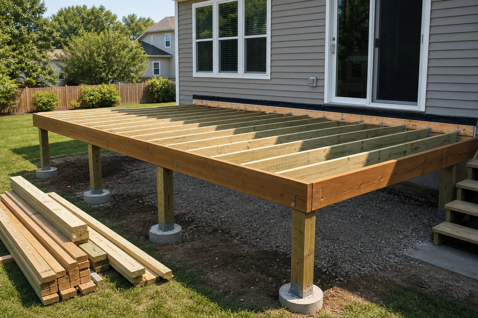
Start with the site, house, and permit path
A deck starts as a site problem, not a lumber order. Walk the proposed footprint after rain if you can. Note the direction of drainage, soft or recently filled soil, slopes, retaining walls, tree roots, buried utilities, overhead service lines, septic components, and places where digging equipment cannot reach. Measure from known property lines instead of using a fence as the boundary. Record doors, windows, vents, hose connections, meters, and the finished floor level at the house.
Contact 811 before digging and follow the notice and ticket rules for your state. Decide where excavated soil, concrete, lumber, and deliveries can go without blocking an exit or damaging a neighbor's property.
Next, ask the local authority having jurisdiction—the building department or other office that enforces the locally adopted rules—what it needs. Confirm zoning setbacks, easements, permit triggers, the adopted code edition, local amendments, design loads, frost and soil information, required drawings, and inspection stages. The International Code Council's current scope and administration material explains the model-code framework, but a model code becomes enforceable through local adoption and can be amended. A section number from a current model book is not proof of the rule in your town.
The City of Portland's deck plan guidance is a useful local example. It asks for site, structural, and elevation information and separates a prescriptive route from an engineered route. That is Portland's process, not a national checklist. Use it to understand the level of detail an office may request, then follow your own jurisdiction's instructions.
Make the permit path part of the schedule. Ask which work must remain visible for inspection and whether an inspection is required before concrete placement. A passed inspection at one stage does not approve hidden future work, and a material list does not reserve an inspection date.
Decide whether the deck is attached or freestanding
An attached deck uses the house as part of its load path. The ledger—the horizontal board that connects deck joists to the building—must transfer vertical and lateral forces into suitable structural framing. Siding, brick veneer, stone veneer, trim, and sheathing are not automatically that framing. You need to identify what is behind the exterior finish, how the floor system is built, whether the band or rim area is sound, and whether the proposed connection has an accepted detail.
Do not choose “attached” just because it saves a row of posts. The American Wood Council DCA 6 guide is based on the 2015 IRC and gives a defined prescriptive path with important limits. It also identifies situations where its ledger details do not apply, including attachment through certain veneers or to a house overhang. The guide itself says construction and materials require approval by the authority having jurisdiction and does not promise acceptance in any particular jurisdiction.
A freestanding or non-ledger deck carries vertical loads through its own beams, posts, and footings. It can avoid a questionable house connection, but it is not structurally independent by name alone. It still needs a complete lateral-load path, suitable footing locations, bracing or other approved stability details, and careful clearance from the house. The local reviewer may have specific requirements for a deck built close to a foundation.
Sketch both options before committing. For the attached option, show the ledger, house framing, flashing path, joist direction, beam, posts, and lateral connections. For the freestanding option, show both support lines and how the frame resists movement. Compare excavation access, doors and steps, drainage, existing utilities, material use, and the amount of professional or field verification required.
If the house framing is hidden, damaged, unusual, or made from a system that does not fit the accepted prescriptive detail, stop treating the connection as a routine DIY choice. A registered design professional or an approved freestanding design may be the cleaner path.
Sketch loads and spans before choosing lumber
Framing size follows the load path. It does not start with whatever lumber is on sale. Draw the decking direction, joist direction, supports, beam lines, posts, and footings. Mark the clear span between supports and any overhang separately. Then identify the area carried by each joist, beam segment, post, and footing. This carried area is often called tributary area.
The 2024 IRC deck section is a current model-code reference for wood-framed exterior decks. It ties deck design to required live or ground-snow loading and directs conditions outside its prescriptive provisions to the structural-design path. Your locally adopted edition may differ, so use the version and tables accepted by your reviewer.
Do not copy a span from a photo, forum post, or different species. Joist and beam capacity depends on member size, grade, species, wet-service conditions, spacing, load, span arrangement, and sometimes incising or treatment. A table is usable only when your project matches its notes and limits. This article deliberately does not reproduce span tables because a number separated from those conditions is easy to misuse.
Flag concentrated and unusual loads early. A hot tub, masonry feature, outdoor kitchen, roof, privacy wall, large planter, or heavy finish can change the framing and footing design. DCA 6 specifically places large concentrated loads such as hot tubs outside its scope. High snow, drifting snow, unusual wind or seismic exposure, multi-level geometry, long cantilevers, and complex shapes may also take the project outside a simple prescriptive path.
Write the selected species, grade, treatment, joist spacing, beam assembly, spans, and load assumptions on the plan. If a lumber substitution is proposed later, run the span check again. “Same nominal size” does not mean “same capacity.”
Lay out footings and posts
Footings begin with the support sketch. Drop a line from each beam reaction to a post and from each post to a footing. Check that the footing locations do not collide with utilities, the house foundation, window wells, drain lines, septic components, retaining walls, or protected tree roots. A neat equal spacing is not useful if one footing lands in disturbed fill or cannot be inspected.
Footing area depends on the load delivered to it and the soil's allowable bearing value. Footing depth also depends on local frost rules, undisturbed soil, site drainage, and the accepted design. Do not use a generic depth from another state or rely on a calculator's regional default as a field decision. Confirm the local design basis and what the inspector needs to see at the bottom of the excavation.
Dig to sound, undisturbed bearing material as required by the accepted plan. Keep loose soil, standing water, organic material, and collapsed sidewall material out of the bottom. If excavation reveals fill, groundwater, buried debris, roots, soft soil, or a foundation condition different from the plan, pause and get direction. Making the hole wider or adding random concrete is not a substitute for a revised bearing decision.
Set forms, reinforcement, anchors, and post bases exactly as the accepted detail and product instructions require. Keep wood separated from soil and manage water so the post base does not sit in a persistent wet pocket. Verify the post-base model, anchor, connector coating, concrete edge distances, and installation sequence before the truck or mixer starts. Hardware from different systems is not automatically interchangeable.
Establish control lines and elevations before placing concrete. Recheck the diagonals, beam line, post centers, top elevations, and clearance to the house. Photograph the open holes and installed components if local policy permits, but photographs do not replace a required inspection. Leave the work accessible until the inspector or design professional says that stage can be covered.
Handle the ledger and water management
Ledger work is both structural and waterproofing work. First expose enough of the wall to identify sound structural framing. Confirm that the proposed ledger location clears doors, vents, and vulnerable transitions. Rot, insect damage, wet sheathing, an unsupported rim area, an engineered floor system without an accepted attachment detail, or a veneer-only connection is a stop sign.
Use the fastening schedule and edge distances from the locally accepted detail. Deck screws, nails, anchors, and structural screws are different products; a familiar-looking screw is not automatically rated for a ledger. Install the specified fastener diameter, length, pattern, washers, and pilot holes for the actual house and ledger materials. Keep the lateral connection separate in your mind: ledger fasteners that carry vertical load do not automatically complete every lateral-load requirement.
Water must be directed out and over the exterior, not trapped behind the ledger. Coordinate the ledger flashing with the wall's water-resistive barrier, siding, door pans, and any existing flashing so water sheds in layers. Protect the top and ends of vulnerable wood as the accepted detail requires. Do not seal a bad drainage path behind a bead of caulk and call it flashed. DCA 6 includes ledger flashing and water-contact limits, but use the detail accepted for your wall assembly.
Treated wood can be more corrosive to steel than untreated dry framing. The treatment chemistry, retention, moisture, coastal or chemical exposure, and contact between different metals all matter. Simpson Strong-Tie's treated-wood FAQ says connector and fastener materials must be compatible and warns against pairing stainless connectors with galvanized fasteners. Its broader corrosion guidance also says no single coating guideline covers every environment. Read the lumber end tag, connector literature, fastener approval, and local requirements together.
Have the ledger, flashing, and house connection reviewed while they are visible. Once decking and trim cover the work, correcting a missed fastener, torn barrier, or reverse lap becomes much harder.
Frame beams, joists, blocking, and stairs
Build from fixed control lines, not from the assumption that every board is straight and every foundation corner is square. Set posts plumb, cut them to the planned beam elevation, and install the specified post-to-base and post-to-beam connections. A beam perched beside a post with ordinary screws is not the same load path as an approved bearing or connector detail.
Assemble built-up beams according to the accepted fastening and splice detail. Place splices only where the design allows. Check crown direction and reject pieces with damage that affects the intended use. Before setting joists, verify beam spacing, bearing, overhang, and the ledger or second support line one more time.
Lay out joists from a consistent reference so decking seams, picture framing, stairs, guards, and openings have support where they need it. Install hangers with the connector manufacturer's listed fasteners, filling the required holes. Do not substitute drywall screws, general-purpose deck screws, or a different nail simply because it fits through the hole. Add blocking and rim members where the plan requires load transfer, joist restraint, guard-post support, decking edges, or stair attachment.
Treat stairs as a small structure, not leftover framing. Resolve total rise from actual finished grades and finished deck elevation. Coordinate the stair opening, stringer design, tread and riser materials, bottom landing, handrail, guard transitions, headroom, and lighting with the locally accepted plan. Field-cut stringers can lose capacity quickly if the geometry or lumber differs from the approved detail.
Before covering the frame, check plumb, level, square, connector installation, fastener completeness, treated cuts, bearing, blocking, and the full lateral path. If a duct, pipe, cable, or unexpected house condition forces a framing change, do not notch or drill first and ask later. Get an approved revision or professional direction.
Install decking with movement and drainage in mind
Decking is the weather surface, but it is not a roof. Water and debris need a path between and away from boards. Keep the framing plane even, provide the support required at board ends and pattern changes, and correct trapped-water details before fastening the first course.
Follow the current instructions for the exact decking product. Wood moisture and width can change as boards dry or take on moisture. Composite and PVC products have product-specific support, end-gap, edge-gap, overhang, fastening, and temperature rules. Do not apply one universal gap to every material. Check the installation guide for the product, the temperature and moisture conditions at installation, and the direction or pattern you plan to use.
Start from a straight reference and regularly check accumulated width. Plan seams and breaker boards so every end has proper support. A diagonal pattern or picture frame may need different joist spacing or added framing; confirm that before buying stock. Predrill where the manufacturer calls for it, keep fasteners aligned, and avoid overdriving heads or crushing hidden clips.
Joist-top tape can be a useful optional water-management layer when it is compatible with the wood, fasteners, and exposure. It does not repair poor flashing, make untreated cuts durable, or replace drainage. Wraps and membranes can also trap water if installed without a complete path out.
Leave access to work that still needs inspection. After fastening, remove metal filings and construction debris that can stain or hold moisture. Check that gaps are open, water can leave the house connection, board ends are supported, and no screw or clip was omitted during a rushed final run.
Plan guards, handrails, and inspections
Do not decide guard requirements by eyeballing one corner. Finished deck height can vary around a sloped site, and local rules define where and how the measurement is taken. Confirm the adopted trigger, guard height, opening limits, stair-guard rules, handrail shape and continuity, landing requirements, and loads with the local reviewer. A low edge at the house does not settle a higher outside corner.
Guard posts and their connections deserve their own framing detail. The load has to move from the top of the guard through the post, bolts or approved connector, blocking, rim, joists, and the deck structure. Surface screws into a rim board are not a design. Proprietary cable, glass, aluminum, or composite systems also need their current evaluation information, manufacturer details, compatible framing, and any locally required engineering.
Plan the inspection sequence before work starts. Common stages may include open footing excavations, framing and connections before concealment, and a final review, but the actual stages and notice rules are local. Ask your building department which stages apply and how much notice it requires.
Make an inspection walk-through before the official visit. Keep the approved plans and product documents available. Clear access to footings, ledger, lateral connectors, guards, stairs, and hardware. Check that changes are marked and approved, required labels remain readable, and work has not been covered too early. Do not coach yourself to hide a deviation; resolve it.
Final approval is not a paperwork formality. It is the point when the authority confirms the completed work under its process. Do not represent a planning model, supplier list, passed footing visit, or contractor opinion as permission to occupy the deck.
Build a material takeoff without pretending it is final
Once the accepted layout is stable, use the BuildListCalc Deck Material Calculator to organize a planning takeoff. Enter the measured length, projection, height, attached or freestanding choice, ledger condition, decking family and profile, stock length, joist spacing, support layout, guards, stairs, footing assumptions, region, framing species and grade, exposure, and fastener approach that match the plan. The tool is designed around a rectangular residential planning model.
Read the visual plan before the price. Confirm joist direction, beam and post arrangement, guards, stairs, and the house side. Then read the planning details and warnings. The tool can estimate decking, fascia, joists, rim boards, beams, posts, blocking, ledger materials, flashing, connectors, fasteners, footings, guards, and stair components. It does not produce a permit set, an engineered span schedule, verified soil capacity, an approved ledger detail, or an inspection result.
Review every material row by assembly. Compare installed quantity with rounded purchase quantity, stock length, package size, waste, and pricing basis. Separate items that are ready for a supplier check from allowances and review items. Confirm exact connector models, approved fasteners, treatment compatibility, field-cut treatment, concrete requirements, decking instructions, stair details, delivery, taxes, and local availability outside the generic quantity pass.
Keep a revision note. If the approved beam line, joist size, species, guard system, stair geometry, footing layout, or decking product changes, rerun the takeoff and recheck downstream hardware. Do not hand a supplier an old list after the structural plan has moved.
A useful takeoff reduces missed categories and supports quote conversations. It is not final until it has been reconciled with the accepted drawings, current product documents, field measurements, local review comments, and the supplier's actual units.
Final pre-order and pre-inspection checklist
Before ordering, put the plan, field notes, product documents, and takeoff side by side.
- Confirm property lines, setbacks, easements, utilities, drainage, and access against the actual site.
- Confirm the permit status, adopted requirements, approved drawings, inspection sequence, and any engineering conditions with the authority having jurisdiction.
- Confirm attached or freestanding support, house framing, ledger eligibility, lateral path, and flashing detail.
- Confirm loads, spans, species, grade, treatment, joist spacing, beam assembly, posts, footings, soil basis, and frost basis against the accepted design.
- Confirm every connector and fastener by model, coating or base metal, approved use, required fastener, and exposure compatibility.
- Confirm stair, landing, guard, and handrail details from finished grade through the complete load path.
- Confirm decking support, pattern framing, gaps, fasteners, and movement rules from the current product instructions.
- Reconcile the BuildListCalc material list with the approved plan and current supplier packaging. Mark allowances, quote-first items, and anything still unresolved.
Before each inspection, stop and look at the work as if you did not build it. Is the required area visible? Does the installed condition match the approved drawing? Are all connector holes and specified fasteners complete? Are treated cuts protected? Can water drain? Are field changes documented? Is access safe?
If the answer is uncertain, pause. Calling the inspector, designer, manufacturer, or supplier before covering the work is usually cheaper than explaining the hidden condition later. The goal is not to make the project look finished as fast as possible. The goal is a deck whose site decisions, load path, water management, materials, and review record agree with one another.